hvac-solutions Products
HVAC Solutions

Flow Switch

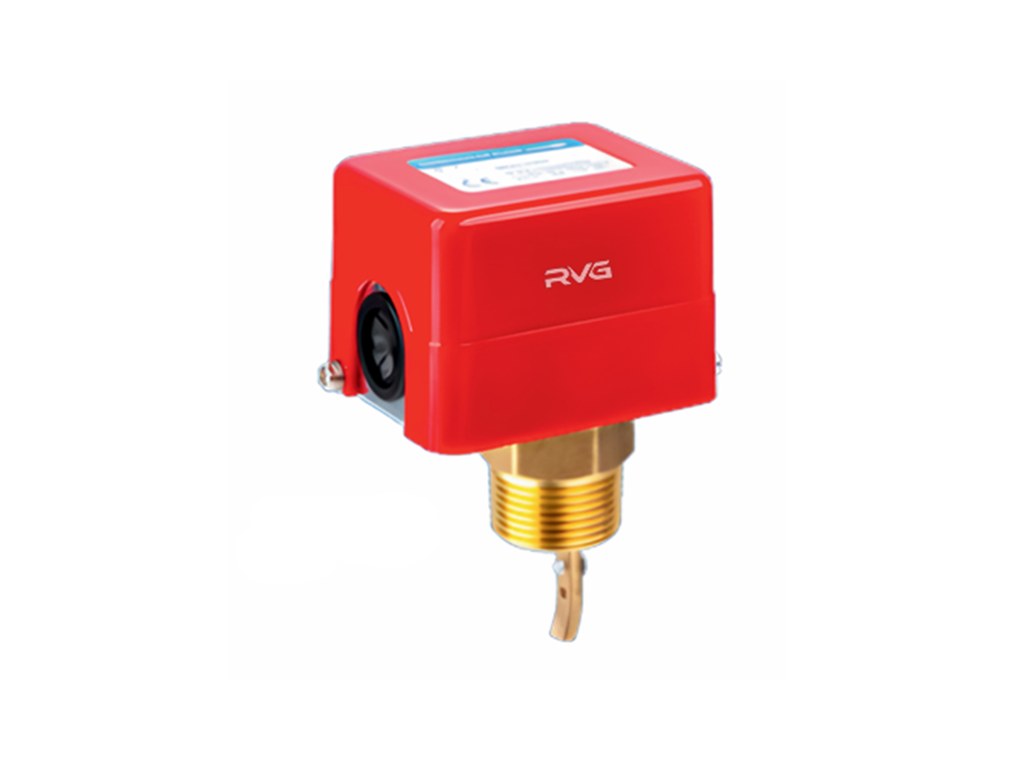
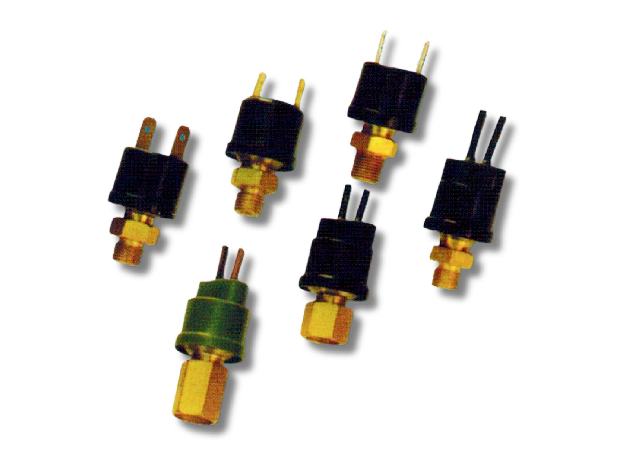
The Flow Switch is a reliable and efficient device designed to monitor liquid flow in pipelines used in HVAC and fluid handling systems. It detects flow conditions and activates or deactivates electrical contacts when flow exceeds or drops below preset levels, ensuring system safety and control. Built with a durable stainless steel paddle and a sealed enclosure, it offers long-lasting performance, easy installation, and dependable operation across a wide range of pipe sizes and applications.

Features

  • Wide Operating Pressure Range: Suitable for liquid pressures up to 1 MPa, offering broad application flexibility.
  • Adjustable Stainless Steel Paddle: Equipped with a three-section stainless steel paddle, designed for pipe diameters ranging from 25–75 mm. The paddle can be trimmed or sections removed to suit specific application requirements.
  • Extended Application Capability: The RVFS Series includes an additional 6” paddle, enabling use in larger pipelines of 100–150 mm diameter.
  • Adjustable Set Point: The switching point is fully adjustable, allowing users to fine-tune the flow setting according to system requirements.
  • Sealed Enclosure Design (RVFS1061): The RVFS1061 model features a fully enclosed housing, providing effective protection against dust and moisture (minor condensation may occur).
  • Reliable Electrical Safety: The RVFS1061 series switch assembly is fully sealed, ensuring safe operation and preventing leakage risks even in the presence of slight condensation.
  • User-Friendly Wiring: The RVFS1001 and RVFS1061 series offer spacious wiring compartments for easy installation.
  • Optional Stainless Steel Connection (Ammonia Compatible): The RVFS1001 / RVFS1061 series can be supplied with stainless steel connections suitable for ammonia-based media. Specify by adding “S” to the model number (e.g., RVFS1061S).

Flow Required for switch actuation

Pipe Diameter 25 32 40 50 65 80 100 125 150 200 100* 125* 150* 200*
Minimum
Adjustable Setting
Flow Increase (Red–Blue Contacts Closed) 0.95 1.32 1.7 3.11 4.09 6.24 14.8 28.4 43.2 85.2 8.4 12.9 16.8 46.6
Flow Decrease (Red–Yellow Contacts Closed) 0.57 0.84 1.14 2.16 2.84 4.32 11.4 22.9 35.9 72.7 6.13 9.31 12.26 38.6
Maximum
Adjustable Setting
Flow Increase (Red–Blue Contacts Closed) 2.0 3.02 4.36 6.6 7.84 12 29.1 55.6 85.2 172.6 13.4 26.8 32.7 94.26
Flow Decrease (Red–Yellow Contacts Closed) 1.93 2.84 4.09 6.13 7.23 11.4 27.7 53.4 81.8 165.8 17.3 25.21 30.66 90.85
  • THE ABOVE FLOW VALUES ARE FOR REFERENCE AND SELECTION PURPOSES ONLY.
  • VALUES MARKED WITH (*) INDICATE PERFORMANCE WITH ALL FOUR PADDLE SECTIONS INSTALLED; UNMARKED VALUES CORRESPOND TO THREE PADDLE SECTIONS.
  • THE MGS FLOW SWITCH ALLOWS SELECTION AND CONFIGURATION OF DIFFERENT PADDLE LENGTHS BASED ON THE PIPELINE FLOW VELOCITY AND INSTALLATION CONDITIONS.

Need Assistance?

Chat with Us
Chat with Us ×
Scan to Chat on WhatsApp
WhatsApp QR
Scan to Chat on WeChat
WeChat QR